Abstract: CAN bus is one of the most widely used fieldbuses in the world. It has been used more and more in China. The multi-motor backlash control mode is often used in large-scale radar antenna control systems, mainly to eliminate the gear gap of its turntable. This paper is based on the CAN bus and PCC-based high-precision multi-motor anti-backlash antenna control system as the background, focusing on the control principle of the system and software and hardware design.
1 Introduction In high-precision antenna control systems (such as tracking satellite communication antennas), precision tracking and azimuth control place very high demands on the accuracy of the antenna's drive system. However, due to mechanical machining errors, mechanical wear, and a certain gap between transmission gears, it not only affects the tracking accuracy of the antenna control system, but also affects the stability of the antenna control system. Therefore, the clearance between the transmission gears must be eliminated to improve the transmission accuracy.
To solve this problem, people think of many ways. The traditional method is to improve the mechanical transmission structure. However, from the known methods of eliminating gear gaps, they always have one or more deficiencies such as a complicated structure, a large size, and poor carrying capacity. Therefore, traditional anti-backlash methods cannot be used in high-precision antenna control systems. The control system uses multiple motors to eliminate the gear gap in the transmission mechanism, thereby improving the transmission accuracy.
Based on the above analysis, the system uses a programmable computer controller (PCC) and CAN bus control system. The multi-motor anti-backlash antenna control system is widely used in antenna control systems, especially for the anti-backlash of large-scale radar antenna turntables. This case uses the currently popular CAN bus technology and PCC and other industrial control products to provide a full set of solutions for multi-motor control in order to realize the anti-backlash, azimuth, and pitch control functions of the antenna turntable. The program has the following features:
(1) The use of CAN bus to network four DC governors not only realizes full digital control, but also has simple structure, simple data communication and high reliability.
(2) Digital speed regulators have torque equalization and loop control functions.
(3) Achieving the turntable's azimuth and pitching bi-directional rotation equalization anti-backlash.
(4) Efficient and accurate control algorithm can realize accurate positioning of antenna control system, target tracking, pitching, ring sweeping, and fan sweeping.
(5) Realize the operation of three motors, two motors or single motors (power reduction).
2 CAN bus introduction CAN, called "Controller Area Network", namely controller local area network, it is one of the buses that use in the world most extensively. It is a multi-line protocol widely used in the automation field and a serial communication network that effectively supports distributed control or real-time control. CAN's applications range from automotive, mechanical, medical equipment, construction environments, and many other areas of the industrial automation industry.
The main reason why CAN bus can be widely used is as follows:
(1) Powerful error detection capability and differential drive function.
(2) It still works well in very harsh environments.
(3) The CAN bus is also very flexible in terms of transmission medium and line design.
The CAN bus has the following main features:
(1) Low cost.
(2) Extremely high bus utilization.
(3) Long transmission distance (up to 10km).
(4) High-speed data transmission rate (up to 1 Mbit/S).
(5) Reliable error handling and error detection mechanisms.
(6) Messages corrupted due to an error during transmission can be automatically resent.
(7) The node has the function of automatically exiting the bus in case of a serious error.
3 Implementation scheme 3.1 Overall framework of system design The multi-motor anti-backlash antenna control system adopts B&R's Programmable Automation Controller (PCC) as the main controller and adopts the high-level language BASIC programming hardware included in its Automation Studio integrated software platform. The driver and speed PID algorithm realizes the networking control of four DC controllers through CAN bus communication, thereby achieving the coordinated control of the drive motors of the four turntables and jointly driving a turntable. To achieve the sharing of torque and the elimination of the transmission gap, thereby improving the system tracking accuracy.

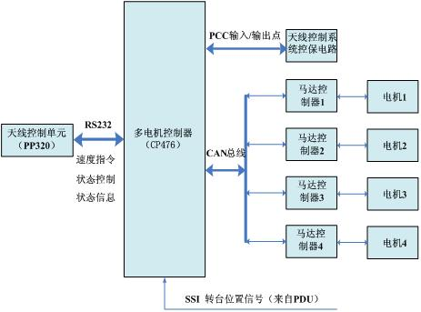
Fig.1 Control network structure of multiple motor anti-backlash antenna control system
The control network structure of the multi-motor anti-backlash antenna control system is shown in Figure 1. The antenna control unit (that is, the human-machine interface HMI, using the B&R PP320 touch screen) passes through the internal IMA and the multi-motor controller (PCC's central processor module CP476 ) Communication is performed between remote control operations such as speed commands, status control, and status information. Four DC drives are controlled by the CAN bus network, and the position signals of the turntable are read by the SSI; the signal acquisition of the control circuit of the antenna control system is controlled by the multi-motor controller (CP476) through its I/O points (DM465 digital Amount of I/O modules). This scheme not only achieves full digital control, but also has a simple structure, a clear interface, and high reliability. It can be seen that the application of multi-motor controller (CP476) and CAN bus is the key.
3.2 Control principle For a four-motor coordinated control of a turntable, to achieve gear backlash, two of them should work as a speed control mode, as the main motor for anti-backlash drive, provide an active drive torque consistent with the direction of rotation of the antenna. The other two are to work as a torque control mode, as a backlash-driven driven motor, to provide backward engagement “tension force” for the backlash mechanism.
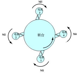
The antenna control unit HMI (PP320) sends the speed commands to the multi-motor controller (CP476) via the serial interface RS-232. The multi-motor controller (CP476) realizes the speed of the four DC converters (Europe) via the CAN bus. Control and torque control switching to achieve a gapless transmission of the antenna turntable. as shown in picture 2.

Figure 2 The control principle of four motor-driven turntables
When the turntable rotates clockwise, the motor 1 and 3 are set to the speed control operation mode, and the motors 2 and 4 are the current control operation mode. Motors 1 and 3 are active motors, motors 2 and 4 are driven motors. M1, M2, M3, and M4 represent torques of motor 1, motor 2, motor 3, and motor 4, respectively. The total torque provided is M = (M1+M3-M2-M4). When the turntable rotates counterclockwise, the situation is just the opposite. Motors 2 and 4 are in speed control mode. Motors 1 and 3 are in current control mode. Motors 2 and 4 are active motors, motors 1 and 3 are driven motors. The total torque provided is M=(M2+M4-M1-M3).
For two DC governors operating in the current control mode, the external current command is given to generate a torque that is opposite to that of the active motor, maintaining a certain tension.
For two DC speed controllers that work in speed control mode, the multi-motor controller (CP476) accepts the speed command of the antenna control unit. After being processed, it is sent to the European direct current governor via the CAN bus and will be compared with the motor feedback speed. After the deviation into the DC drive speed loop, through the torque bias, the output current signal to the current loop, after PID operation, the current signal to the motor armature. Thus, the speed and current closed-loop control of the turntable motor are realized, and the backlash of the turntable is realized. System control block diagram shown in Figure 3.

Fig. 3 Block diagram of the turntable drive motor control system
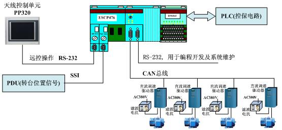
4 System Design 4.1 System Hardware Design The hardware structure of the system is shown in Figure 4.

Figure 4 system hardware structure
In the hardware design, the system selects the PCC of B&R as the core control unit, and realizes the networking of four DC governors and their direct current motors through the CAN bus. The antenna control unit, the control unit and the turntable position signals communicate through the communication respectively. The expansion interface constitutes a complete antenna control system.
In this system, the PCC uses the CAN bus network to control the operation of the DC motor. This not only greatly simplifies the electrical wiring, but also greatly eases the installation and maintenance of the system. The PCC can control the motor with high speed and high precision, and the PCC is in direct current. The real-time status information monitoring of the governor is more specific and comprehensive. From the current development status of high-mobile radar and other vehicle-mounted computer control systems and monitoring systems in the industry, the widespread application of the CAN bus has become an inevitable technological trend.
4.2 System Application Software Design The application software of the multi-motor control system is based on the PCC-based development platform AutomationStudio integrated software platform design, which fully utilizes the hardware and software advantages of the standardized industrial controller PCC:
(1) All PCC software is built in a modular structure. The functions of each module are relatively independent, and they are related to each other through data interfaces. This facilitates collaborative development and maintenance, and facilitates archiving and standardization of projects. The relatively independent design style of each task module can effectively ensure that the impact on the control software will be local and single when the system device or process requirements change.
(2) The application software of the multi-motor control system adopts an object-oriented style and is constructed by multi-level multi-modules. The control strategy program of the motor has nothing to do with the underlying data acquisition and the underlying communication program, which is conducive to local changes and equipment expansion of the project. , The project software code can get the maximum degree of reusability.
(3) The software of the multi-motor control system is all made in BASIC high-level language. The software has good readability and easy maintenance.
(4) The use of CAN bus to control multiple DC motors (drivers) is also one of the most salient features of the software design of this system. PCC can control the motor movement through the CAN bus at high speed and high precision to realize multiple motors. Perform comprehensive information acquisition and real-time monitoring, including speed, direction, start/stop, enable, and set current control of each motor, and monitor the current speed, direction, start/stop, enable state, and motor current of the motor. And fault status and other information.
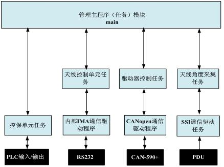
4.3 Modular structure of application software The application software of this system makes full use of the structuring and modular design features of the application software of B&R's Automation Studio integrated software platform. According to the system hardware structure and process design requirements, the application software of the entire system is designed into a plurality of relatively independent task modules. Each module passes information in accordance with the strictly defined interface specifications. The relatively independent design style of each task module can effectively ensure that when the system device or process requirements are changed, the impact on the control software is local, centralized, and single. The structure of the entire application software system is shown in Figure 5.

Figure 5 Structure of Application Software System
4.3 Fault-tolerant design In order to ensure the reliable operation of the mechanical and electrical components of the entire antenna control system, the system has made the following fault-tolerant design for antenna control:
(1) When a DC governor triggers an alarm for any reason, the motor driven by the governor cannot move in accordance with the control command. To prevent accidents from occurring, this system does a safety protection measure— — Stop all motor movements. Through the displayed error code, the operator can be intuitively informed to handle the accidental troubleshooting.
(2) When the control circuit collects the trigger of the limit signal, the control program of the multi-motor control system will stop the motor in a protective manner so that the turntable does not touch the mechanical limit member, causing the motor to stall.
5 Conclusion Based on CAN bus and PCC all-digital multi-motor anti-backlash antenna control system to achieve the anti-backlash of the antenna turntable and azimuth, pitch and other control functions. Application practice shows that the system can not only achieve accurate positioning of the antenna system, but also has a simple structure, smooth data communication, high reliability, and good motor drive characteristics.
References [1] Qi Rong, Xiao Weirong. Programmable computer controller technology. Beijing: Electronic Industry Press, 2005.
[2] Zhou Ligong. CAN basic knowledge.
Author brief introduction Wang Jielei male, born in 1981, undergraduate, research direction for automation engineers. Since 2008, he has been a project engineer of Shanghai Yingshuo Automation Technology Co., Ltd. Now he is mainly engaged in program design and field application.


