Privacy statement: Your privacy is very important to Us. Our company promises not to disclose your personal information to any external company with out your explicit permission.

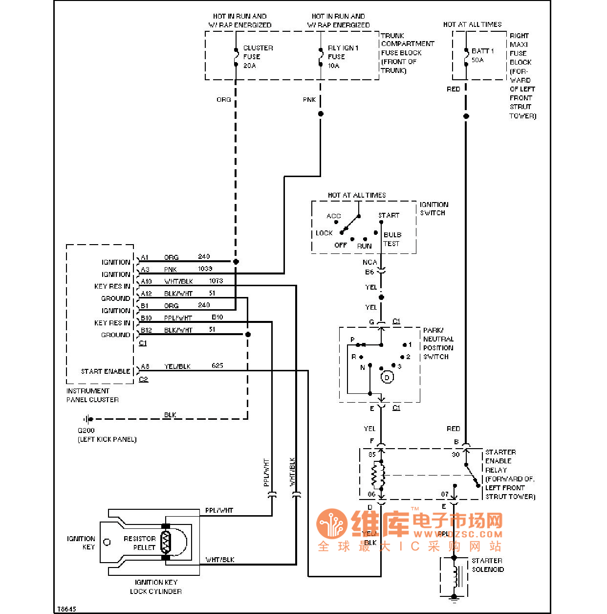
As shown in the figure, the Cadillac electric antenna circuit diagram
Power supply part:
Power supply voltage: Depending on the power requirements of the antenna and the device specifications, direct current (DC) or alternating current (AC) power supply may be used, and the voltage range can range from a few volts to tens of volts.
Power management: May include power supply filters, regulators or converters to ensure that a stable and clean power supply is provided to the antenna.
Control part:
Control circuit: Usually a microcontroller, logic circuit or application-specific integrated circuit (ASIC) is used to control the actions of the antenna, such as lifting, rotating, etc.
User interface: May include switches, buttons or remote controls for manual control of the antenna.
Communication interface: If the antenna needs to communicate with external devices (such as GPS receivers, radar systems, etc.), corresponding communication interfaces and protocols are also required.
Drive part:
Motor driver: used to drive the antenna motor and control the direction, speed and position of the motor.
Motor: Electric antennas usually use DC motors or stepper motors to achieve actions such as lifting, rotating, etc.
Sensor and feedback part:
Sensors: May include position sensors, speed sensors, etc., used to detect the current state of the antenna.
Feedback circuit: Convert the output signal of the sensor into a signal that the control circuit can understand to achieve closed-loop control.
Protection part:
Overcurrent protection: prevents the motor driver or motor from being damaged by overcurrent.
Overheat protection: prevents the motor or other electronic components from being damaged by overheating.
Electromagnetic interference (EMI) protection: reduces the impact of external electromagnetic fields on the circuit, and reduces the impact of electromagnetic radiation generated by the circuit on other devices.
Other parts:
Indicator and display: used to display the status or error information of the antenna.
Connectors and cables: used to connect the power supply, control circuit, drive circuit and the antenna itself.
Wifi Antenna, Router Antenna, Patch Antenna
Email ke pemasok ini

Privacy statement: Your privacy is very important to Us. Our company promises not to disclose your personal information to any external company with out your explicit permission.

Fill in more information so that we can get in touch with you faster
Privacy statement: Your privacy is very important to Us. Our company promises not to disclose your personal information to any external company with out your explicit permission.